![]()
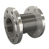
KRS-11 PN 16
Loose Flanged
Rotary flange expansion joints are one of the axial expansion joint types and are special expansion elements that absorb thermal expansions occurring in the pipeline along the axis. These expansion joints minimize the stresses and structural loads that may occur in the pipes by controlling the longitudinal extensions and contractions occurring in the system.
Piping systems are usually divided into different expansion sections and stabilized with fixed points placed at strategic points. In this way, the thermal movement occurring in a certain area is met only by the axial expansion joint placed specifically for that area. In this way, both the integrity of the system is preserved and energy loss and maintenance requirements are reduced.
Technical Information
Standard Production : AISI 321 (DIN 1.4541)
Special Production : AISI 304 (DIN 1.4541), AISI 309 (DIN 1.4828), AISI 316 (DIN 1.4401), AISI 316 ti (DIN 1.4571) etc
Design Pressure : 16 BAR
Design Temperature : – 196 + 550 C
Standard Flange : Rst 37-2 (DIN 1.0038) PN 2.5 – PN 6 – PN 10 – PN 16
Special Flange : Stainless Steel DIN – BS – EN – ANSI etc.
Standard Liner : AISI 321 – DIN 1.4541
Special Liner : AISI 304 (DIN 1.4541), AISI 309 (DIN 1.4828), AISI 316 (DIN 1.4401), AISI 316 ti (DIN 1.4571) etc
Technical Drawing
Applications
To absorb axial expansions, reduce stress and noise in the system, all machines, all motors, all pumps, industrial applications, exhaust applications, gas and water lines, drinking water lines, etc.
Paint Information
Flanges between DN 25–DN 300 are cadmium plated. For sizes DN 300 and above, specially painted flanges resistant to corrosion are used. It offers high durability and long-lasting use for industrial systems.
Special Note
If requested, the design temperature can be increased to +950°C. Contact us for special requests. Flange tables are in the technical tables section. Product weights have a tolerance of ±10%. Liner is recommended for abrasive fluids.
DN ø | L mm | ø d mm | ø Do mm | +/- AX mm | AX N/mm | KEA cm² | Flange Outer Diameter D mm | Flange Hole Center k mm | Flange Thickness b mm | Flange Hole Number n | Hole Diameter e mm | Approximate Weight Kg Kg |
| 25 | 120 | 36 | 45 | 10 | 86 | 12 | 115 | 85 | 16 | 4 | 14 | 2,70 |
| 32 | 130 | 44 | 53 | 15 | 60 | 18 | 140 | 100 | 16 | 4 | 18 | 4,10 |
| 40 | 130 | 50 | 62 | 15 | 60 | 24 | 150 | 110 | 16 | 4 | 18 | 4,10 |
| 50 | 150 | 61 | 77 | 17 | 88 | 37 | 165 | 125 | 18 | 4 | 18 | 5,10 |
| 65 | 160 | 77 | 97 | 19 | 89 | 58 | 185 | 145 | 18 | 4 | 18 | 7,20 |
| 80 | 170 | 90 | 115 | 24 | 80 | 82 | 200 | 160 | 20 | 8 | 18 | 8,00 |
| 100 | 175 | 117 | 146 | 24 | 89 | 134 | 220 | 180 | 20 | 8 | 18 | 10,00 |
| 125 | 195 | 142 | 170 | 26 | 68 | 192 | 250 | 210 | 22 | 8 | 18 | 8,00 |
| 150 | 220 | 169 | 199 | 26 | 130 | 265 | 285 | 240 | 22 | 8 | 22 | 17,00 |
| 200 | 220 | 220 | 254 | 36 | 158 | 442 | 340 | 295 | 24 | 12 | 22 | 26,00 |
| 250 | 235 | 275 | 315 | 27 | 230 | 683 | 405 | 355 | 26 | 12 | 26 | 37,00 |
| 300 | 320 | 328 | 393 | 23 | 665 | 1019 | 460 | 410 | 28 | 12 | 26 | 52,00 |
| 350 | 320 | 365 | 419 | 23 | 713 | 1205 | 520 | 470 | 30 | 16 | 26 | 73,00 |
| 400 | 330 | 410 | 476 | 20 | 812 | 1538 | 580 | 525 | 32 | 16 | 30 | 91,00 |
| 450 | 340 | 460 | 526 | 20 | 919 | 1897 | 640 | 585 | 32 | 20 | 30 | 117,00 |
| 500 | 350 | 508 | 569 | 20 | 1009 | 2273 | 715 | 650 | 34 | 20 | 33 | 142,00 |

