![]()
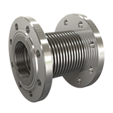
KRS-2 30-60mm
Fixed Flanged
Rotating flanged expansion joints are special expansion elements that belong to the axial compensator group and are designed to absorb thermal expansions occurring in pipelines along the pipe axis. These compensators offer ease of installation thanks to their flanged connection systems and provide practical advantages, especially in systems that require regular maintenance.
To effectively control thermal expansion, the piping system is divided into various expansion zones in accordance with engineering principles. Each expansion zone is isolated from the others through fixed points, thereby increasing the stability of the system. With this structure, the axial movement occurring in each expansion zone is absorbed and balanced by rotating flanged expansion joints that are specifically positioned for that zone.
Technical Information
Standard Production : AISI 321 (DIN 1.4541)
Special Production : AISI 304 (DIN 1.4541), AISI 309 (DIN 1.4828), AISI 316 (DIN 1.4401), AISI 316 ti (DIN 1.4571) etc
Design Pressure : 16 BAR
Design Temperature : – 196 + 550 C
Standard Flange : Rst 37-2 (DIN 1.0038) PN 2.5 – PN 6 – PN 10 – PN 16
Special Flange : Stainless Steel DIN – BS – EN – ANSI etc.
Standard Liner : AISI 321 – DIN 1.4541
Special Liner : AISI 304 (DIN 1.4541), AISI 309 (DIN 1.4828), AISI 316 (DIN 1.4401), AISI 316 ti (DIN 1.4571) etc
Technical Drawing
Applications
To absorb axial expansions, reduce stress and noise in the system, all machines, all motors, all pumps, industrial applications, exhaust applications, gas and water lines, drinking water lines, etc.
Paint Information
Flanges between DN 25–DN 300 are cadmium plated. For sizes DN 300 and above, specially painted flanges resistant to corrosion are used. It offers high durability and long-lasting use for industrial systems.
Special Note
If requested, the design temperature can be increased to +950°C. Contact us for special requests. Flange tables are in the technical tables section. Product weights have a tolerance of ±10%. Liner is recommended for abrasive fluids.
|
DN ø |
L mm |
ø d mm |
ø Do mm |
+/- AX mm |
AX N/mm |
KEA cm² | Flange Outer Diameter D mm | Flange Hole Center k mm | Flange Thickness b mm | Flange Hole Number n | Hole Diameter e mm | Approximate Weight Kg Kg |
| 25 | 120 | 36 | 45 | 10 | 86 | 12 | 115 | 85 | 16 | 4 | 14 | 2,70 |
| 32 | 130 | 44 | 53 | 15 | 60 | 18 | 140 | 100 | 16 | 4 | 18 | 4,10 |
| 40 | 130 | 50 | 62 | 15 | 60 | 24 | 150 | 110 | 16 | 4 | 18 | 4,10 |
| 50 | 150 | 61 | 77 | 17 | 88 | 37 | 165 | 125 | 18 | 4 | 18 | 5,10 |
| 65 | 160 | 77 | 97 | 19 | 89 | 58 | 185 | 145 | 18 | 4 | 18 | 7,20 |
| 80 | 170 | 90 | 115 | 24 | 80 | 82 | 200 | 160 | 20 | 8 | 18 | 8,00 |
| 100 | 175 | 117 | 146 | 24 | 89 | 134 | 220 | 180 | 20 | 8 | 18 | 10,00 |
| 125 | 195 | 142 | 170 | 26 | 68 | 192 | 250 | 210 | 22 | 8 | 18 | 8,00 |
| 150 | 220 | 169 | 199 | 26 | 130 | 265 | 285 | 240 | 22 | 8 | 22 | 17,00 |
| 200 | 220 | 220 | 254 | 36 | 158 | 442 | 340 | 295 | 24 | 12 | 22 | 26,00 |
| 250 | 235 | 275 | 315 | 27 | 230 | 683 | 405 | 355 | 26 | 12 | 26 | 37,00 |
| 300 | 320 | 328 | 393 | 23 | 665 | 1019 | 460 | 410 | 28 | 12 | 26 | 52,00 |
| 350 | 320 | 365 | 419 | 23 | 713 | 1205 | 520 | 470 | 30 | 16 | 26 | 73,00 |
| 400 | 330 | 410 | 476 | 20 | 812 | 1538 | 580 | 525 | 32 | 16 | 30 | 91,00 |
| 450 | 340 | 460 | 526 | 20 | 919 | 1897 | 640 | 585 | 32 | 20 | 30 | 117,00 |
| 500 | 350 | 508 | 569 | 20 | 1009 | 2273 | 715 | 650 | 34 | 20 | 33 | 142,00 |

